Manufacturing Steps
The manufacturing routing defines the sequence of operations needed to produce a part. Each step is associated with an activity, a machine and an estimated time.
Prerequisites
- Have entered the technical data for the part
- Have configured your company's activities and machines
Concepts
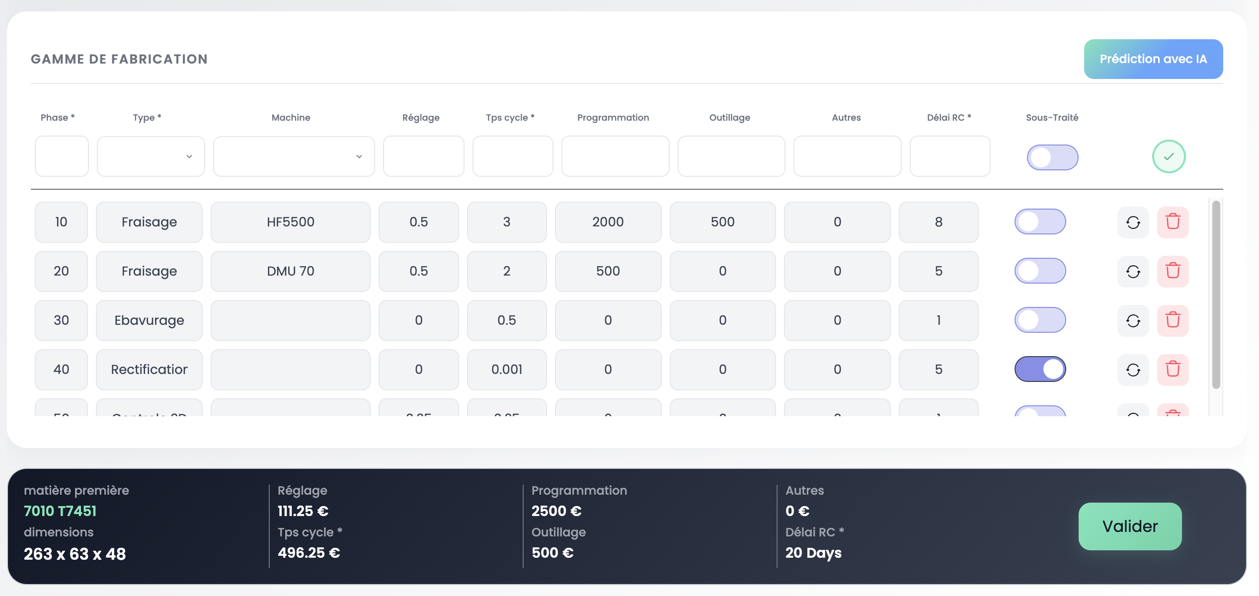
Step (Phase)
A step is a single operation in the routing. It contains:
| Field | Description |
|---|---|
| Phase | Order number in the routing (10, 20, 30...) |
| Type | Associated activity (Milling, Deburring, Grinding, etc.) |
| Machine | Production equipment used (if applicable) |
| Setup | Setup time (in hours) |
| Cycle time | Estimated unit time (in hours) |
| Programming | CNC programming cost (NRC — Non-Recurring Cost) |
| Tooling | Tooling cost (NRC) |
| Other | Other NRC costs |
| SC Lead time | Total phase lead time in working days: includes wait times, resource processing times and transfer times as needed |
| Subcontracted | ON/OFF toggle — indicates if the step is subcontracted |
INFO
The Programming, Tooling and Other columns are non-recurring costs (NRC): they apply only once, regardless of order quantities.
TIP
When the Subcontracted toggle is enabled, only the phase number and activity type are required. Machine times and costs do not apply. The SC Lead time entered here will not be used in cycle calculations — the lead time entered by purchasing will take precedence.
Activity vs Machine
There are two types of activities:
- Direct activity (e.g. Deburring, Assembly, Grinding): the activity has its own hourly rate. No machine to select.
- Machine activity (e.g. Milling, Turning): the activity points to a production equipment (machine) which has its own hourly rate.
Each activity and machine is configured in the Activities & Machines settings.
How to
Step 1 — Open the routing
From the Engineering view, select a part. The routing displays in the central panel.
Step 2 — Add a step
Click on the first empty row of the table. Enter:
- Phase: step number (10, 20, 30...)
- Type: select the activity from the list
- Machine: select the production equipment (if the activity requires it)
- Setup and Cycle time: estimated times
- NRC: programming, tooling, other costs if applicable
- Subcontracted: enable the toggle if the step is subcontracted
Step 3 — Apply a template
Coming soon
Applying step templates directly from the routing will be available in a future release.
Summary
The bottom bar of the routing summarizes key data:
| Data | Description |
|---|---|
| Raw material | Alloy and stock dimensions |
| Setup | Total setup cost |
| Cycle time | Total cycle time cost |
| Programming | Total NRC programming |
| Tooling | Total NRC tooling |
| Other | Total NRC other |
| SC Lead time | Total subcontracting lead time |
The Validate button confirms the routing and sets the part status to Validated.
AI Time Prediction
MPX Engine includes a prediction engine that estimates machining times from the 3D geometry and your company's production history.
Launch a prediction
Click the AI Prediction button at the top right of the routing.

Prediction result
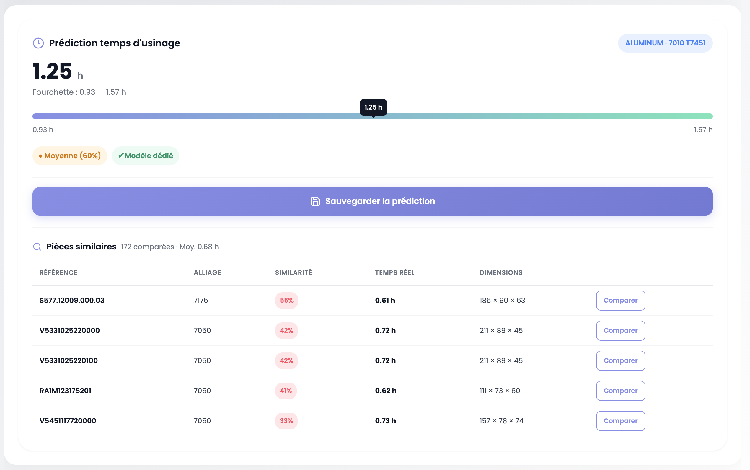
The prediction panel displays:
- Target time: the predicted value (e.g. 1.25 h)
- Range: confidence interval (e.g. 0.93 — 1.57 h), visually represented by a progress bar
- Confidence index: prediction reliability, based on the results of algorithms specific to your company (Average, Dedicated model)
- Material: badge showing the detected alloy
Similar parts
Below the prediction, a table lists similar parts found in your production history:
| Column | Description |
|---|---|
| Reference | Part number of the historical part |
| Alloy | Part material |
| Similarity | Similarity index (%) — the higher it is, the more comparable the part is in terms of geometry, dimensions and material |
| Actual time | Machining time actually recorded in production |
| Dimensions | Historical part dimensions |
| Compare | Button to open the detailed comparison |
Compare with history
Click the Compare button to open a side-by-side view between your analyzed part and the reference part.
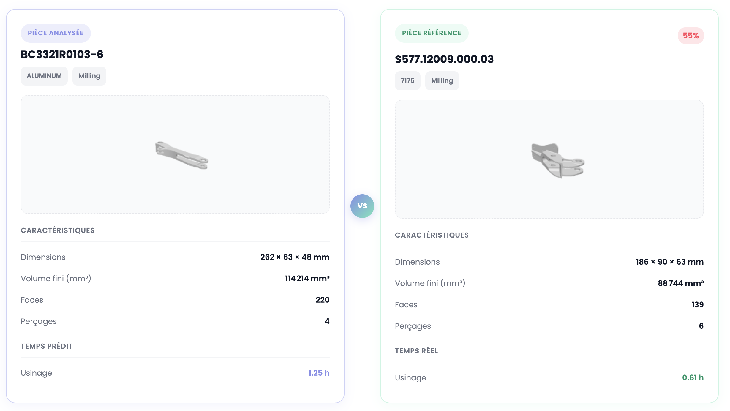
The comparison displays for each part:
- 3D visualization of the model
- Characteristics: dimensions, finished volume, number of faces, number of holes
- Time: predicted time (analyzed part) vs actual time (reference part)
This allows you to visually validate the prediction's relevance by comparing the geometric complexity of both parts.
Save the prediction
Click Save prediction to record the result. This enables:
- Shop floor feedback: later compare the predicted time with the actual production time
- Dynamic model training: each feedback loop improves the accuracy of future predictions
Important
The predicted time does not automatically populate the manufacturing routing. It is up to the user to manually enter the value in the Cycle time field of the relevant step. This lets you keep control and adjust the value if needed.
Validation

The bottom bar of the routing summarizes key part data: raw material, setup costs, cycle time, NRC (programming, tooling, other) and total SC lead time.
Click the Validate button to confirm the routing. This sets the part status to Validated in the Engineering table.
INFO
Once all parts in the Engineering table are validated, remember to validate the Engineering step of the overall RFQ workflow via the Workflow Validation selector at the top of the page.

Important Notes
TIP
Cycle times directly feed into cost calculation in the Pricing section. Be as accurate as possible.
Next step
Move on to the Purchasing section to manage supplier consultations and material costs.