Technical Data
The Engineering page centralizes all technical data for your parts: hierarchical nomenclature, classification, raw material, surface treatments, special processes and dimensions. This data is largely pre-filled by the BOM extraction, but you can adjust it manually.
Prerequisites
- Have imported and extracted data for your RFQ
The Engineering Table
The table displays all parts in the RFQ in a hierarchical view (assemblies → child components).
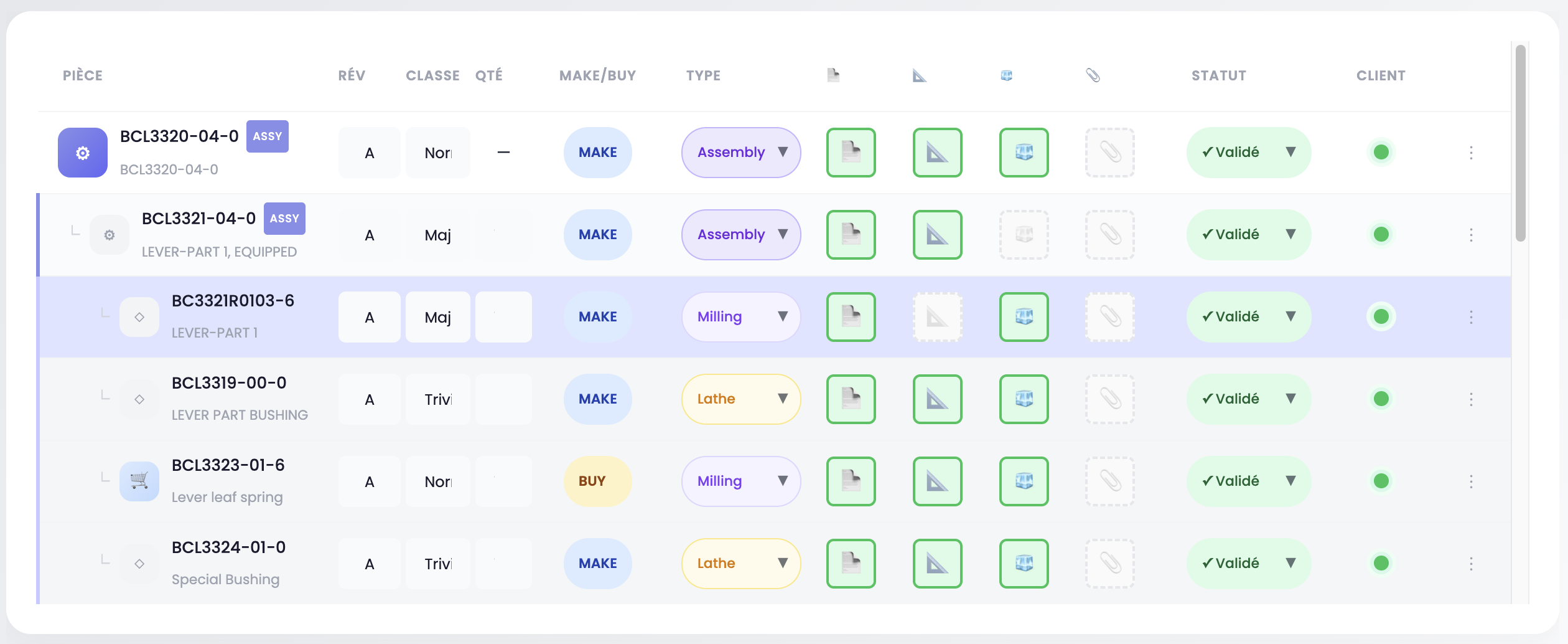
Table columns
| Column | Description |
|---|---|
| Part | Part number, designation and icon. Assemblies carry the ASSY badge. No-Bid parts carry the NOBID badge (greyed-out row). Child components are indented under their parent |
| Rev | Drawing revision (editable) |
| Class | Part classification (editable) |
| Qty | Quantity in parent assembly (editable for children, "—" for top-level parts) |
| Make/Buy | Manufacturing decision: Make (in-house) or Buy (purchase) |
| Type | Machining type: Milling, Lathe, Millturn, Assembly, Standard |
| 📄 | Article sheet / BOM file |
| 📐 | Drawing file |
| 🧊 | 3D file (STEP) |
| 📎 | Miscellaneous file |
| Status | Pending or Validated |
| Customer | Detected customer badge (end user) |
| ⋮ | Actions menu |
Editing table data
The Rev, Class and Qty fields are editable directly in the table. Click the field, modify the value — saving is automatic.
The Make/Buy, Type and Status selectors are dropdowns. Select the desired value, the change is immediate.
TIP
The machining type is automatically filled in when a 3D file is available for the part. Recognized types are: Milling, Lathe and Millturn. You can always change it manually if needed.
File management
Each part displays its associated files in the 📄 📐 🧊 📎 columns. You can:
- Drag and drop a new file directly onto the corresponding cell
- Click on an existing file to view or download it
- Delete a file via the ✕ button
WARNING
Deleting an article sheet file (📄) also deletes the associated technical data (material, treatments). Deleting a 3D file (🧊) removes volumetric data.
Actions menu (⋮)
Click the ⋮ button on the right side of each row to access the contextual menu:
| Action | Description |
|---|---|
| + Add child | Adds a child component under this part |
| 🗑 Delete | Deletes the component (only available for children without sub-components). A double-click is required to confirm |
Selecting a part
Click on a table row to select the part. A detail panel appears below with:
Program & Quantities
The associated aircraft program and quantities per year over the contract duration.
Surface treatments and Special processes
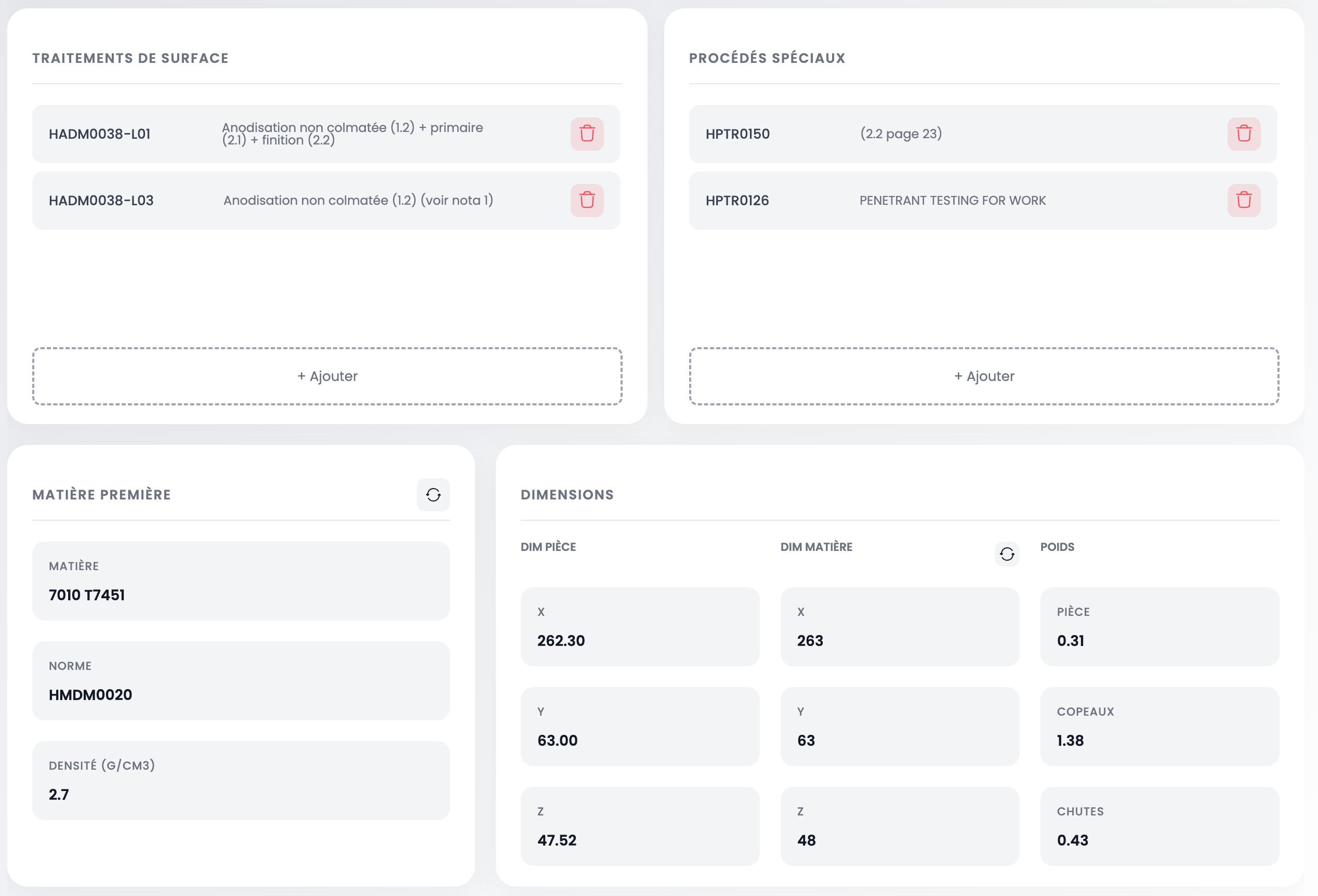
These two sections display data automatically extracted from the customer's documents:
Surface treatments — list of identified treatments (e.g. Non-sealant anodizing, Sand blasting). Each entry shows the spec/standard code and description.
Special processes — list of identified processes (e.g. Penetrant testing, welding). Each entry shows the code and description.
For each section, you can:
- Delete a treatment or process by clicking the 🗑 button on the right side of the row
- Add a treatment or process by clicking + Add at the bottom of the section
Adding a treatment or process
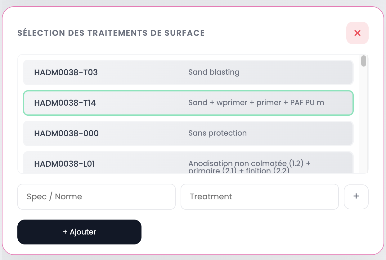
A modal opens with:
- The list of available treatments/processes from your company's catalog. Click a row to select it (highlighted in green)
- Manual input fields (Spec / Standard and description) at the bottom of the modal, with a + button to create a free entry
- The + Add button to confirm the addition
Raw material
The Raw material card displays:
| Field | Description |
|---|---|
| Material | Identified alloy (e.g. 7010 T7451) |
| Standard | Material specification (e.g. HMDM0020) |
| Density | Material density in g/cm³ |
WARNING
Material directly impacts machining time prediction and material cost calculation. An error here affects the entire quote.
Changing the material
Click the ⚙ icon next to the Raw material title to open the selection modal.
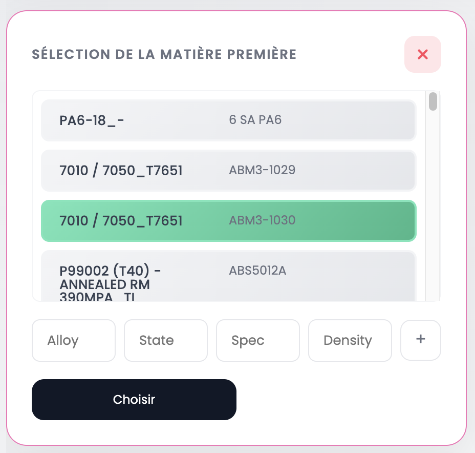
The modal displays your company's material catalog. Each row shows the alloy and specification. Click a row to select it (highlighted in green), then click Choose to confirm.
You can also create a custom material by filling in the fields at the bottom of the modal: Alloy, State, Spec, Density, then click +.
Dimensions
The Dimensions card displays data extracted from the 3D file (STEP):
| Data | Description |
|---|---|
| Part Dim (X, Y, Z) | Part bounding box dimensions in mm |
| Material Dim (X, Y, Z) | Raw material dimensions in mm |
| Weight | Part weight in kg |
| Chips | Removed material weight in kg |
| Offcuts | Residual material weight (raw - part - chips) in kg |
INFO
Dimensions and weights are automatically calculated from the STEP file. If no 3D file is associated, these fields remain empty. You can edit material dimensions via the ⚙ icon.
Next step
Once technical data is verified, view the 3D model of your parts to check geometry and dimensions.