3D Model
The built-in 3D module lets you visualize STEP models of your parts directly in the application. It displays the part geometry, raw material and dimensions.
Prerequisites
- Have imported a STEP file associated with the part
Interface
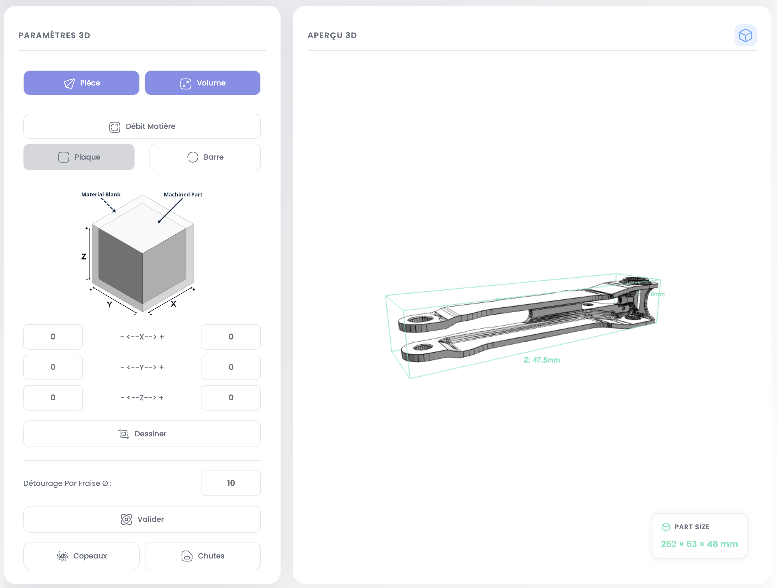
The screen is split into two areas:
- 3D Parameters (left): raw material configuration and allowances
- 3D Preview (right): interactive model visualization
Navigation
| Action | Mouse | Trackpad |
|---|---|---|
| Rotate | Left click + drag | Two fingers + drag |
| Zoom | Scroll wheel | Pinch |
| Pan | Right click + drag | Two fingers + Shift |
Available Views
Two buttons at the top of the parameters panel allow you to display:
- Part: the 3D model of the part, displayed in metallic gray
- Volume: the OBB as a green wireframe (oriented bounding box)
OBB (Oriented Bounding Box)
The green wireframe surrounding the part in the preview. It represents the smallest oriented box enclosing the geometry. X, Y, Z dimensions are shown on the Part Size card at the bottom right.
INFO
Check whether the customer's documentation requires a specific grain direction on the material. If so, the OBB and raw material orientation must respect this constraint — allowances should be adjusted accordingly.
Raw Material
The semi-transparent orange volume represents the stock material from which the part will be machined. Check Raw Material to display it. Two possible shapes:
- Plate (rectangular block) for milling parts
- Bar (cylinder) for turning parts
Configure Raw Material
Plate Mode
The diagram illustrates the 6 allowance faces. Adjust values on each axis:
- X- / X+: X allowance (mm)
- Y- / Y+: Y allowance (mm)
- Z- / Z+: Z allowance (mm)
Click Draw to update the raw material visualization.
The Edge trimming cutter Ø field simulates cutting the part with a cutter of the specified diameter (in mm). This updates the offcut and chip volumes to reflect actual machining conditions.
Click Validate to recalculate the final volumes.
The Chips and Offcuts buttons at the bottom of the panel display the calculated volumes.
Bar Mode
Adjust:
- Diameter: bar diameter (mm)
- Long- / Long+: length allowance (mm)
Click Validate to recalculate the turning volume.
Switch Mode
You can force a different raw material type than the one automatically detected:
- Click Plate to switch to rectangular block mode
- Click Bar to switch to cylindrical mode
INFO
When you switch modes, MPX Engine automatically calculates the new raw material dimensions from the 3D geometry.
Next step
Create the manufacturing routing to define machining operations for each part.